Liquid Mirror Telescope: Basics
A rotating liquid surface takes the shape of a paraboloid under the constant pull of gravity and the centrifugal acceleration, which grows stronger with the distance from the central axis (E. Cappoci, 1850). The parabolic shape occurs because a liquid surface always sets its local surface perpendicular to the net acceleration it experiences, which in this case becomes stronger and more inclined with distance from the central axis.
Consequently, a Liquid Mirror Telescope can be made by using a liquid mirror as the primary mirror and by putting a camera at the focal point of the paraboloid.
Liquid mirror telescopes are Zenithal pointing telescopes: they can only see a small field of view around the Zenith (point along the local vertical direction). Pointing objects, as done when using classical technology telescopes, is no longer possible. Integrating images with LMTs is done using a new real-time imaging technique called Time Delayed Integration (TDI) (described below).
Thanks to the Earth rotation, the telescope scans a strip of constant declination equal to the latitude of the observatory. Because a LMT observes the same region of the sky night after night, it is possible either to co-add the images taken on different nights in order to improve the limiting magnitude attainable with a LMT, or to subtract images taken on different nights to make a variability study of the corresponding strip of sky. Consequently, a LMT is very well suited to perform photometric variability studies of the strip of sky it observes.
The ILMT piece by piece:
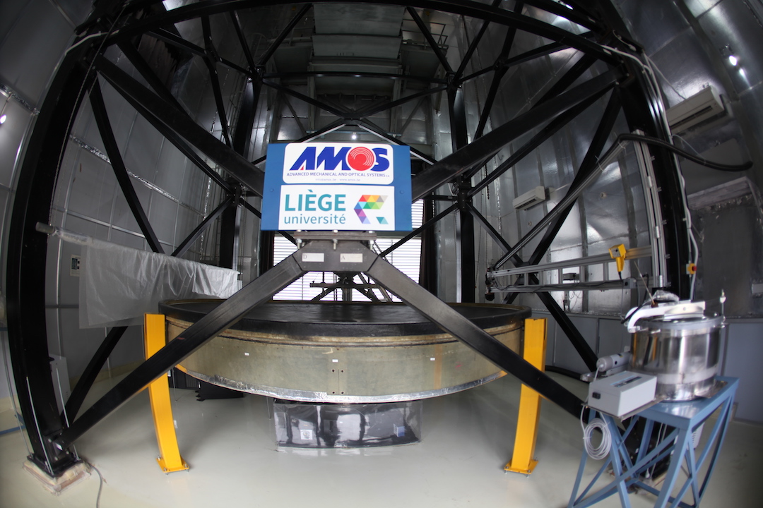
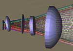
The International Liquid Mirror Telescope (ILMT) is made of three main components: a primary rotating mirror, a focal structure and an upper-end. The upper-end is itself composed of a CCD camera and optical corrector.
Let us describe the different components of the ILMT.
The Primary Mirror:
The primary mirror is made of a 4m diameter container resting on a turntable. The container and the turntable are mounted on a a three-point mount that aligns the rotation axis parallel to the gravitational field of the Earth. A thin layer (approximately 3 mm) of mercury is then spread on the container. In order to guarantee the good optical quality of the mirror, the liquid mercury must stay as stable and stationary as possible. Consequently, all sources of perturbations (such as vibrations or any transitory effects) that could propagate to the mercury layer must be avoided as much as possible. This stability requirement for the mercury implies very strict specifications for the turntable and the container.
A parabolic liquid mirror is made by rotating a highly reflective liquid (mercury). As we all know, a perfect reflecting paraboloid represents the ideal surface for a mirror to focus parallel rays of light into a single point.
The turntable:
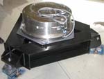 The turntable is a commercial air bearing that is driven by a synchronous motor controlled by a variable-frequency AC power supply stabilized with a crystal oscillator. It has to support the container full of mercury. The choice of an air bearing system has been made in order to avoid the transmission of vibrations from the turntable to the mercury. To avoid transitory effects in the mercury, requirements on the rotation speed stability are very strong (relative variations in the rotation period must be smaller than 10^(-6) ).
The container:
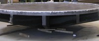 The container is a very important component of the system. It is light and rigid. It is made with Kevlar laminated over a foam core (Hickson, Gibson & Hogg 1993). Moreover, this container must fulfill strict specifications of rigidity, temperature stability , etc. in order to guarantee a final shape as perfect as possible and to avoid the formation of wavelets over the mercury surface.
Structure:
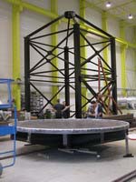 The structure supports the telescope upper-end and its alignment mechanism. This structure is very simple as the telescope is kept vertical. As the upper-end must be located at the focal point of the paraboloid, the structure height is a little higher than the focal length of the mirror: 8 meters!
CCD Camera:
 The ILMT is equipped with a CCD camera whose sensor is a 4096 by 4096 pixel matrix. Both the Liège University (IAGL; Special Research Funds, Large equipments) and the Royal Observatory of Belgium (ROB; LOTTO grant) have contributed to the purchase of the ILMT 4Kx4K CCD camera. As previously written, LMTs are not able to track celestial objects as conventional telescopes do. In the case of the ILMT, tracking is done electronically, by using the special CCD readout technique known as Time Delayed Integration (TDI). Taking an image with a CCD camera is usually done in two steps. First, the sensor pixel matrix is exposed to the light of the source which is imaged. During the exposure, photoelectrons are generated and stored in the pixels of the sensor. The number of photoelectrons generated in a pixel is proportional to the flux of light arriving in this pixel during the exposure. Secondly, the number of photoelectrons in each pixel is counted: this step is called the CCD readout. Classical read out of a CCD is done by successively drifting each column of the sensor pixel matrix to an electronic device, the register located just next to the sensor, which counts the number of photoelectrons in all the pixels of each column. In the TDI mode, the drift of the columns is slowed down. In the case of the ILMT, as a star goes through the field of view of the telescope, its image crosses the sensor. The drift of the columns is slowed down in such a way that photoelectrons generated by the star are drifted over the sensor at the same speed as the image of the star travels through the focal plane. Consequently, as soon as a star gets out of the field of view, the number of photoelectrons it has generated is counted. So TDI is a real time imaging technique. At each moment, the ILMT creates an image of the field of sky passing at the zenith.
Corrector:
As the primary mirror is parabolic, the off-axis imaging is distorted by several aberrations (mostly distortion, spherical and coma). In order to correct these and to increase as much as possible the field of view of the telescope, an optical corrector is inserted before the CCD camera. It does also remove the TDI distortion. Indeed, while using a classical corrector, the TDI technique degrades the images. This comes from the fact that the TDI technique moves the electrons along a straight line over the CCD at a constant speed while the stellar images move at different speeds along distinct curved trajectories. The deformation depends on the latitude of the observatory (it is zero at the equator and increases with latitude). Optical design shows that it is possible to eliminate these effects by introducing an adverse deformation of the field thanks to the designed TDI corrector. The final goal of the corrector is to sufficiently compensate the aberrations to permit the ILMT to be a seeing limited telescope imaging a field of 23′ by 23′.